
Solution
50t/d Integrated MBR Device Design Plan
1. Equipment Overview1.1 Equipment OverviewEquipment Type: Domestic Sewage Integrated MBR Treatment DeviceTreatment Object: Domestic SewageTreatment Capacity: 50t/d, 2.5m³/h1.2 Influent Water QualityWith reference to the general influent water quality statistics of urban sewage treatment plants and
1. Equipment Overview
1.1 Equipment Overview
Equipment Type: Domestic Sewage Integrated MBR Treatment Device
Treatment Object: Domestic Sewage
Treatment Capacity: 50t/d, 2.5m³/h
1.2 Influent Water Quality
With reference to the general influent water quality statistics of urban sewage treatment plants and the Handbook of Water Supply and Drainage Design, the design influent water quality of this project is as follows:
Design Influent Water Quality
Index | CODcr | BOD5 | SS | TP | TN | PH |
Value (mg/L) | ≤ 400 | ≤ 200 | ≤ 200 | ≤ 4 | ≤ 40 | 6-9 |
1.3 Effluent Water Quality
The discharge standard is required to meet the first-class A standard of Discharge Standard of Pollutants for Municipal Wastewater Treatment Plants (GB18918-2002), and the main water quality indicators are shown in the following table.
Design Effluent Water Quality
Index | CODcr | BOD5 | SS | NH3-N | TN | PH |
Value (mg/L) | ≤ 50 | ≤ 10 | ≤ 10 | ≤ 8 | ≤ 15 | 6-9 |
1.4 Design Basis
1. Conclusion of the company's MBR pilot experiment;
2. Relevant design standards and specifications: Handbook of Water Supply and Drainage, Code for Design of Outdoor Drainage (GB50014-2006), Discharge Standard of Pollutants for Municipal Wastewater Treatment Plants (GB18918-2002), etc.
2. Sewage Treatment Process
2.1 Selection of Process Route
According to the requirements of effluent water quality for COD, BOD5, TP, and ammonia nitrogen indicators, a comprehensive comparison is made from the aspects of technical feasibility and advancement, water quality stability and operation management convenience, sludge production, resistance to water quality impact load, etc. Considering the environmental requirements of the project area, this plan adopts the improved A2/O + MBR sewage treatment process.
2.2 Selection of Membrane Module
The membrane is an ultrafiltration/microfiltration level membrane. An artificial pressure difference is created on both sides of the membrane, and water is collected through the membrane (permeate). Macromolecular pollutants and activated sludge are retained in the reactor by the membrane, thereby achieving the separation of pollutants and water.
3. Engineering Design
The treatment process adopted by the sewage treatment station is the "A2/O + MBR process".
3.1 Process Flow
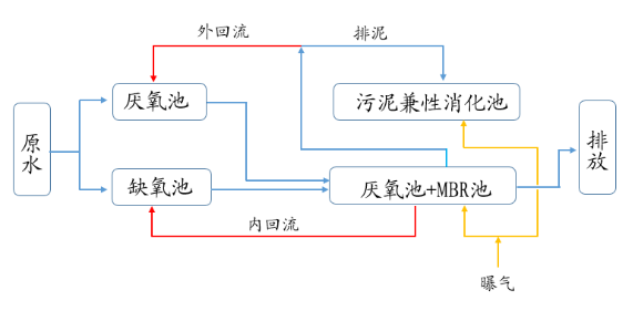
Sewage first enters the lifting well, is lifted by the lifting pump, and enters the regulating tank after intercepting suspended pollutants in the sewage through the grid. The regulating tank plays the role of regulating water volume and balancing water quality. Lifted by the regulating tank lift pump, it passes through the fine grid to further remove suspended solids in the water, and then enters the biochemical tank for biochemical treatment and nitrogen and phosphorus removal. The biochemical tank is divided into anoxic zone, aerobic zone and MBR zone.
The returned sludge from the membrane treatment unit is returned to the anoxic zone through the return pump, the excess sludge is regularly discharged to the sludge tank through the return pump, and the mixed liquid in the aerobic zone is returned to the anoxic zone through the return pump. The sludge in the sludge tank is regularly cleaned and transported to the designated place of the environmental sanitation department for disposal.
The process flow diagram is shown as follows:
Figure 4: Sewage Up-to-Standard Treatment Process Flow Diagram
Note: Picture source: Original document "50t/d Integrated MBR Device Design Plan"
3.2 Process Description
1. Biochemical Tank
A. Anaerobic Zone
B. Anoxic Zone
The function of the anoxic zone is denitrification. In this reactor, denitrifying bacteria use organic matter in sewage as a carbon source to reduce a large amount of NO3- and NO2- brought into the returned sludge from the aerobic tank to N2 and release it into the air. The BOD5 concentration continues to decrease, and the NO3- concentration also decreases significantly.
C. Aerobic Zone
Under aeration conditions, a large number of activated sludge microorganisms繁殖 in the tank are used to remove organic substances in the water through their own degradation or adsorption to achieve the purpose of purifying water quality.
D. MBR Zone
The MBR zone uses membranes to filter the sludge-containing sewage in the biochemical reaction tank to achieve solid-liquid separation. On the one hand, the membrane retains microorganisms in the reaction tank, so that the concentration of activated sludge in the tank is greatly increased to a very high level, making the biochemical reaction for degrading sewage proceed more quickly and thoroughly. On the other hand, due to the high filtration precision of the membrane, most suspended substances are removed, and high-quality produced water is obtained.
The membrane zone is equipped with an MBR membrane module system and supporting water outlet, cleaning, purging and other systems. The purging (aeration) in the MBR membrane zone has two purposes: one is for gas-water oscillation around the membrane module to keep the membrane surface clean, and the other is to provide oxygen required for biodegradation.
The water after biodegradation passes through the MBR membrane module under the suction of the self-priming pump, and the filtrate is collected through the MBR water collection pipe, and then sent to the clear water tank or discharged after disinfection. Through the efficient interception of the membrane, most bacteria and suspended solids are retained in the membrane tank. The MBR membrane module can effectively intercept nitrifying bacteria, so that the nitrification reaction proceeds smoothly and ammonia nitrogen is effectively removed; at the same time, it can intercept difficult-to-degrade macromolecular organic matter, prolong its residence time in the reactor, and make it degraded to the maximum extent.
The MBR membrane module is equipped with a dedicated purging system to purge and shake the membrane elements to prevent sludge from accumulating around the membrane elements and affecting the permeability of the membrane elements. Excess sludge is discharged regularly to control the concentration of activated sludge and sludge age in the system.
④ Clear Water Tank
The effluent from MBR enters the clear water tank for storage for cleaning the membrane system.
⑤ UV Disinfection
The effluent from the clear water tank is disinfected by UV to ensure that the total number of bacteria in the treated effluent is qualified and discharged up to the standard.
3.3 Design Parameters of Structures
This MBR integrated equipment adopts the "A2/O + MBR" process. The design scale of the A2/O + MBR biochemical system is 60t/d, that is, 2.0t/h.
1. Anaerobic Tank
Size: 1.2×2.0×1.25m
HRT: 1.5h
2. Anoxic Tank
Size: 1.0×2×2.3m
HRT: 2.3h
3. Aerobic Tank & Membrane Tank (Combined Construction)
Size: 2.5×2×2.3m
HRT: 5.5h
4. Sludge Digestion Tank
Size: 1.1×1.2×2.0m
5. UV Disinfection Unit
Online UV Disinfector
Quantity: 1 set
Specification: Pipeline type, Q=2.5m³/h, DN25
Description: Installed in the equipment room
6. Equipment Room
Size: 2.0×2.0×2.5m
Quantity: 1 seat
Structure: Carbon steel anti-corrosion integrated equipment
4. Equipment Selection
Table: List of Main Process Equipment
Serial Number | Equipment Name | Quantity | Unit | Remarks | ||
I | ||||||
Coarse Filter Screen | 1 | set | ||||
1 | Primary Lifting Pump | 2 | set | |||
2 | Basket Grid | 1 | piece | |||
II | ||||||
3 | Membrane-Anoxic Return System | 1 | piece | |||
4 | 本体管件及阀门 (Main Body Pipe Fittings and Valves) | 1 | set | |||
5 | MBR Membrane Module | 1 | set | Brand: Beijing Ouweiaite | ||
6 | ||||||
7 | ||||||
III | ||||||
8 | Product Water Pump | 1 | set | |||
9 | CIP Pump | 1 | set | |||
10 | Aeration Blower | |||||
11 | Purging Blower | 1 | set | |||
12 | Sodium Hypochlorite Dosing Pump | 1 | set | |||
13 | Citric Acid Dosing Pump | 1 | set | |||
14 | Sodium Hypochlorite Storage Tank | 1 | piece | |||
15 | Citric Acid Storage Tank | 1 | piece | |||
Total: |
4.3 List of Main Instruments
Table: List of Main Instruments
Serial Number | Name | Quantity | Unit | Installation Location | ||
1 | Static Level Transmitter | 1 | set | Regulating Tank | ||
2 | Static Level Transmitter | 1 | set | Membrane Tank | ||
3 | Pressure Transmitter | 1 | set | Product Water Pipe | ||
4 | Liquid Level Switch | 1 | piece | Clear Water Tank | ||
5 | Liquid Level Switch | 2 | piece | Chemical Storage Tank | ||
6 | Electromagnetic Flowmeter | 1 | set | Suction Pump Outlet Pipe | ||
7 | Float Flowmeter | 1 | set | CIP Pump Outlet | ||
8 | Float Flowmeter | 1 | set | Membrane Tank Blower Outlet Pipe | ||
9 | Float Flowmeter | 1 | set | Aerobic Tank Blower Outlet Pipe | ||
10 | Ordinary Pressure Gauge | —— | piece | Water Pump Outlet | ||
Total: |
Send Your Water Treatment Requirement
Tell us the feedwater, required capacity, target water quality and project conditions. Your inquiry email will automatically include the page you are viewing so our team can understand the exact product, technology or reference that led to your request.
- Feedwater source / available analysis
- Design flow or required production capacity
- Target product-water quality or process duty
- Project country, operating conditions and delivery target